JTQ30(L) automatic transfer switch
Installation & application
The power input terminal shall be connected to 1#, 3#, 5#, 7# terminals of normal
power circuit breaker QN and the reserve power circuit breaker QR. If three-pole
circuit breaker is used, the null lines NN and NR must be connected, three poles
special terminal connected to null line is located between two circuit breakers, in the
process of installation and connection, don't forget the local controller wire originally
connected to the inlet terminal of circuit breaker, or never break it off or make short
circuit, etc..
Operation
When doing manual operation, set the manual-auto button to the manual operation
position, when the handle rotates to the end CW by pushing, the circuit breaker QR will
open, and the circuit breaker QN will close; and on the contrary, when the handle rotates
to the end CCW by pushing, the circuit breaker QR will close, and the circuit breaker QN
will open;
If the power indicator lamp on the panel doesn't go on, this means the input power
has fault, and the switch can't be used. Only the power recovers, the automatic operation
can be done immediately. Set the manual-auto button to the automatic position state,
if the normal power recovers, t he circu it breaker QN will enter into the closing state
automatically, and the normal power (N) indicator lamp on panel will go on; if the normal
power is failure, the switch will transfer to reserve power automatically, the reserve power
(R) indicator lamp will go on. As for the external signal indicator lamp, this device provides
passive signal of 220VAC and max current 500mA.
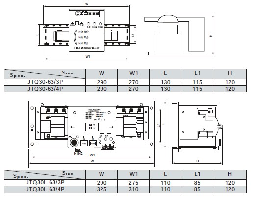
Outline and mounting size


