Open Electric Co.,Ltd.
Open Electric Co.,Ltd.
Products
Search Catalog
|
|||||||||||||||||||||||||||||
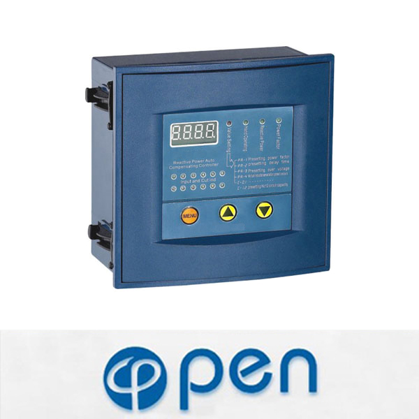
JKW58 series reactive power auto compensating controller
Operation Manual Instruction
A. High compensation precision for counting capacity of capacitor by reactive power;
B.High power factor of measuring precision, wide display area;
C.With automatic distinguish function, automatically keep the voltage signal and current signal in the same terminal;
D.With two working modes of full-automatic and handwork set;
E.Friendly human-computer interface, easy to operate;
F.Different controlling parameter is adjustable in whole digit; it is easy to use at direct-viewing;
G.With two working modes of auto and manual operation;
H.With the protecting function of overvoltage and overcurrent;
I.With the power down function, so the data cannot lose;
J.With low impedance(≤0.01).
1.Introduction
JKW58 series reactive power auto compensating controller is suitable for self-adjusting capacitor Compensating devices in low voltage distribution system and make power factor meet with presetting set by user, therefore it will increase the efficiency of the power transformer, reduce line loss, and improve voltage quality. On final aim it will increase the economic and social benefits.
2.Ambition conditions
a.Altitude not more than 2500m.
b.Ambient temperature:-25°C~50°C
c.Relative humidity:<50% at 40°C and <90% at 20°C
d.On site where it has no corrosive gases, conductive dusts, combustible explosive mediums.
e.On site where it has severe vibration.
3.Technical specifications
Rated working voltage; AC380V 50HZ
Rated working current: AC 0~5A 50HZ
Rated output power: AC220V 7A 50HZ
Displaying power factor; Lag 0.001~forward 0.001
Measured capacity: 0~9999KVAR
Working mode: automatic selecting the best or loop switch
Sensitivity: 100mA
Protection class: IP40 (outer enclosure)
4.Advice for Use
The characteristics of full automatic working mode: This controller has been in the automatic mode before leaving factory. All parameter has been preset according to the most reasonable method. It works normally as long as users connect the wiring correctly.
The characteristics of handwork setting mode: when the load is light at several fields ,and the capacity is big ,the controller goes on input and cut vibration continuously, under this condition ,the handwork setting mode is suitable for using.
5.Selection the full automatic and handwork setting mode
Use the different &#118alue of PR-4 parameter to distinguish and select the working mode of controller (see part 6)If user adjusts this parameter within (1-12),which means the controller is under the automatic mode. And the big and small data means how much the output loop of the controller is .If user adjusts this parameter within (50-40000,which means the controller is under handwork mode, the big and small data means the transformation ratio of user coefficient and total current mutual inductor.
Note: before the controller is not used, the transformation ratio of the actual current mutual inductor and capacity parameter of all capacitor must be input to the controller under the handwork mode.
6.Menu Operation
Operating the Menu Key in turn, the controller will enter into the menu of Power Factor, Reactive Power, Manual operation and Parameter preset circularly.Note:Only after entering into manual operation menu in 2 senconds.could the operation key Menu be entered into parameter adjustment menu. Other menus haven’t this limit.
The reactive power menu will display the symbol AUTO under the full automatic mode.
The parameter preset menu has submenu 16 items under handwork mode .Operating the Menu key in turn, enter into each of submenu separately. when operating the key of increasing and decreasing by degrees ,the target data of each submenu can be preset, and the four-position digitron displays
Menu code and target data alternately. For example:PR-1 means menu code ,098 means target data. The parameter preset menu has submenu 4 items under full automatic mode, that is Power Factor Preset. Delay Preset, Overvoltage preset, Loop preset (preset menu of transformation ratio of public current mutual inductor)
7.Code meaning of submenu under the parameter preset menu:
PR-1 target power factor preset (0.90-0.99) adjustable
PR-2 Time Delay preset (static state 1S-200S) Adjustable
PR-3 Overvoltage preset (400V-500V) Adjustable
PR-4 Current transformation ratio preset (1-12)or (50/5A-4000/5A)
1-12 means output loop quantity of controller, full automatic mode.
50-4000 means transformation ratio at site total current mutual inductor, hand work input mode.
C-01 capacity preset of No.1 capacitor group (0-150Kvar)
…capacity preset of No.12 capacitor group (0-150Kvar)
Note : Code C-01,02,03..12 is one to one correspondence with the control output terminal code of the controller being used for controlling AC contractor. It should be one to one correspondence when input capacity of capacitor. For example, the capacity of capacitor group is 15 kilovar controlled by No.1 input terminal ,the target data of C-01 menu should be adjusted as 15. For the output terminal which is not connected with capacitor, the target date should be adjusted as0
8.Debugging
Warning: During the process of adjustment, user should abide by the following adjustment step. The one with *is the controller is under handwork mode.
A: Assemble the compensating device according to the demand of connection diagram, and then make a detailed examination so as to remove the mistake that may course serious potential safety hazard.
B: Switching in compensating device, the controller enters into automatic state.
Note: If the compensating device is running under non-actual condition, before starting the machine , user should make sure that the current signal lagging voltage signal
*c .input the transformation ratio at site signal current mutual inductor, for the detail shown as Menu operation.
*d. input the capacity of capacitor of each branch circuit, for the detail shown as Menu operation
e. Operate Key Menu to make the handwork operation indicator light, handwork operation acting as a measure of compensating device adjustment can be used for checking if the connection is correct or not,. Operate key increasing by grade, input capacitor group, operate key decreasing by grade cut capacitor group . Note: The output terminal which the correspondent capacitor &#118alue is zero can’t be conduct input and cut action. Without indicator is permitted for the operation mentioned above, but the power factor displayed and reactive power &#118alue is meaningless.
F. In order to make the controller automatically input and cut capacitor group ,besides user should put menu underside menu of power factor, reactive factor ,the current signal lagging voltage signal and system voltage is not higher than overvoltage protective &#118alue and is not lower than under voltage protective &#118alue which condition also is important.

10.Connection diagram
JKW5C perforate dimension:113x113(mm)
Ub,Uc voltage signal input terminal
Ia, In current signal input terminal
V common terminal of control output
terminal
JKW58 perforate dimension:138X138(mm)
11.Type N controller with the function of input an cut vibration closing
The control physical quantity of this controller is reactive power. The advantage of this operational mode is that can effectively avoid input and cutting vibration. In order to realize perfectly safe, this controller adds input and cut vibration closing function. Its meaning is when a certain group capacity appears action two times (one tie each of Input and cutting),after the controller removing action, stopping input and cutting three minutes (except for overvoltage)
12.Explicit Declaration
Overvoltage state* Under power factor, reactive power, manual operation menus, if the digital display unit displays the same numerical &#118alue, that means the controller is overvoltage removal state. the displayed &#118alue is system voltage &#118alue.
CosØ &#118alue 8 Displaying 0985 means present power factor is lagging 0.985 ,displaying
-985 means present power factor is leading 0.985
Undercurrent state* Displaying C0 means undercurrent signal, the current is less than 100mA
13.Fault and Remove
During using and installing the controller, for some easy overlook connection mistakes will result in compensating device abnormally operating, the regular fault phenomena and its removal methods shown as following.
a)Input control head panel, indicating lamp lights, but AC contactor can’t close, This phenomenon caused because the inside coil of AC contactor have not obtained power supply or not enough power User should check whether the type of AC contactor is the same as the drawing ,fuse is perfect, power supply common terminal of AC contactor and output common terminal of controller are connected on the same wiring, and the connection is open circuit or not.
b)With the changing abnormality and no changing of input power factor of capacitor, the former caused be cause of the uncorrected sampling of voltage or current signal ,User should pay more attention to checking signal sampling .The latter caused because of the uncorrected position of user’s signal mutual inductor inserted. The current mutual inductor should be in serted in the output position where shows total load current change (e.g. Total cabinet .bus line)
c)The gauge outfit of controller always displays C—0, this phenomenon caused because of the big or small signal current or no current of controller input .User should calculate whether the transformation ratio of current mutual inductor is rational or not, current signal loop has open circuit or connected with other in struments in series and parallel or not.
d)One group or two groups capacitor never has input (input indicating lamp can’t light ) This phenomenon only will take place when in the handwork operating mode ,but the common reason is that the user did not preset capacity of capacitor or preset too big data when men ds parameters In this case, as long as preset capacity of capacitor once again.
e)The reactive power &#118alue of controller has a wide gas with onsite &#118alue, this phenomenon caused generally because of the uncorrected transformation ratio of current mutual inductor preset. User should check whether the transformation ratio of the signal current mutual inductor is in correspondence with preset &#118alue of not .
f)The power factor &#118alue of controller has a wide gas with onsite &#118alue, There are two possibilities for these phenomena: one is the uncorrected sampling of voltage of current signals; the other is current signal exceeds 5.5A (selecting the transformation ratio of current mutual inductor is unreasonable )
g)If there are some difficult problems and user does not solve by himself, please contact with the local dealer or manufacturer.